Some advices to take into account before doing electrical connections:
To ensure a proper management of the electronic signals the distance between the components should not exceed the following:
CONNECTION BETWEEN COMPACT KIT AND ELECTRIC CONTROL
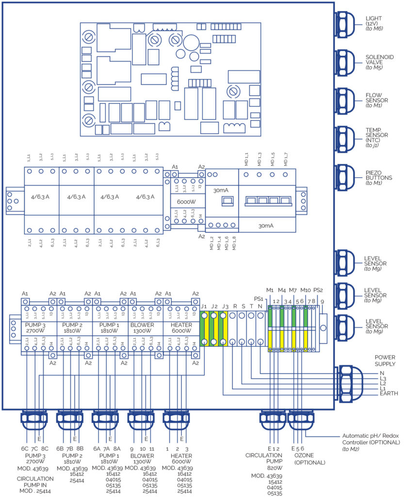
WIRING SECTIONS
Connect cables to their corresponding sections to ensure proper functioning and to prevent potential electrical problems that could affect the user’s safety.
P max [W]
| 20 > L [m] | 20 ≤ L 35 [m] | 35 ≤ L < 55 [m] | |
| Sc [mm2] | 20 | 35 | 55 |
| 0,5 | 882 | 504 | 321 |
| 1 | 1764 | 1008 | 641 |
| 1,5 | 2646 | 1512 | 962 |
| 2,5 | 4410 | 2520 | 1603 |
| 4 | 7055 | 4032 | 2566 |
| 6 | 10583 | 6047 | 3848 |
| 10 | 17638 | 10079 | 6414 |
| 16 | 28221 | 16126 | 10262 |
KIT 43639
| A | |||
| Element | P total [W] | P phase [W] | I phase [A] |
| R | 6000 | 2000 | 9 |
| P.F | 820 | 273 | 1.6 |
| P.2 | 1810 | 603 | 3.2 |
| P.3 | 2700 | 900 | 3.2 |
| B | 1300 | 433 | 3.8 |
| PTC | – | – | – |
| F | – | – | – |
| T | – | – | – |
| B | Sc [mm2] | |||||
Element | P total [W] | P fase [W] | I fase [A] | 20 > L [m] | 20 ≤ L 35 [m] | 35 ≤ L < 55 [m] |
| T | – | – | – | 4 | 6 | 10 |
| N | – | – | – | 4 | 6 | 10 |
| L1-L2-L3 | 14463 | 4821 | 254 | 4 | 6 | 10 |
KIT 16412CE
| A | |||
| Element | P total [W] | P phase [W] | I phase [A] |
| R | 6000 | 2000 | 9.0 |
| P.F | 820 | 820 | 3.8 |
| P.1 | 1810 | 603 | 3.2 |
| P.2 | 1810 | 603 | 3.2 |
| P.3 | 0 | 0 | 0.0 |
| B | 1300 | 433 | 3.8 |
| PTC | – | – | – |
| F | – | – | – |
| T | – | – | – |
| B | Sc [mm2] | |||||
Element | P total [W] | P phase [W] | I phase [A] | 20 > L [m] | 20 ≤ L 35 [m] | 35 ≤ L < 55 [m] |
| T | – | – | – | 4 | 6 | 10 |
| N | – | – | – | 4 | 6 | 10 |
| L1-L2-L3 | 14463 | 4821 | 25,4 | 4 | 6 | 10 |
KIT 04015CE
| A | |||
| Element | P total [W] | P phase [W] | I phase [A] |
| R | 6000 | 2000 | 9.0 |
| P.F | 600 | 600 | 2.7 |
| P.1 | 1050 | 1050 | 4.9 |
| P.2 | 0 | 0 | 0.0 |
| B | 1300 | 433 | 3.8 |
| PTC | – | – | – |
| F | – | – | – |
| T | – | – | – |
| T | – | – | – |
| B | Sc [mm2] | |||||
Elemento | P total [W] | P fase [W] | I fase [A] | 20 > L [m] | 20 ≤ L 35 [m] | 35 ≤ L < 55 [m] |
| T | – | – | – | 2.5 | 4 | 6 |
| N | – | – | – | 2.5 | 4 | 6 |
| L1-L2-L3 | 9012 | 3483 | 17,7 | 2.5 | 4 | 6 |
KIT 05135CE
| A | |||
| Elemento | P total [W] | P fase [W] | I fase [A] |
| R | 6000 | 2000 | 9.0 |
| P.F | 820 | 820 | 3.8 |
| P.1 | 1460 | 1460 | 6.8 |
| P.2 | 0 | 0 | 0.0 |
| P.3 | 0 | 0 | 0.0 |
| B | 1300 | 433 | 3.8 |
| PTC | – | – | – |
| F | – | – | – |
| T | – | – | – |
| B | Sc [mm2] | |||||
Elemento | P total [W] | P fase [W] | I fase [A] | 20 > L [m] | 20 ≤ L 35 [m] | 35 ≤ L < 55 [m] |
| T | – | – | – | 2.5 | 4 | 10 |
| N | – | – | – | 2.5 | 4 | 10 |
| L1-L2-L3 | 9642 | 3893 | 19.6 | 2.5 | 4 | 10 |
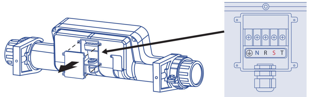
HEATER CONNECTION
The connection of the PTC sensor must be made via an own channel in order to avoid possible interferences. Connect the Heater power supply to the electrical control board as follows:
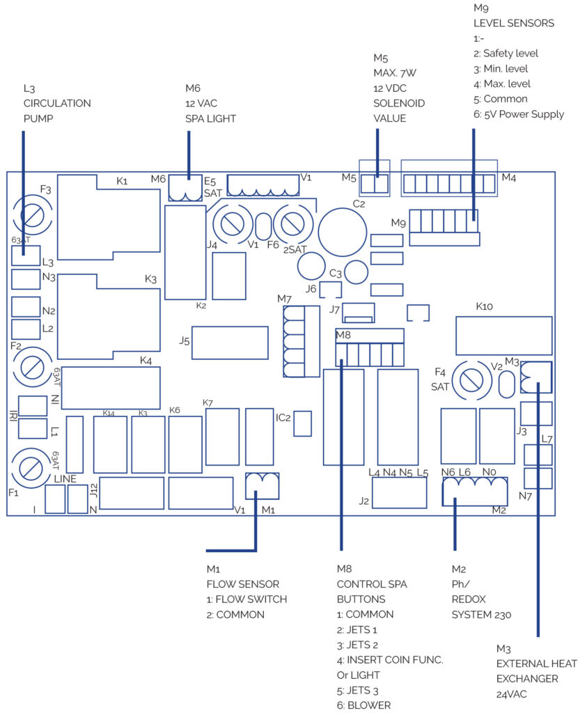
PRINTED CIRCUIT BOARD
REMOTE SPA PUSH BUTTONS CONNECTION
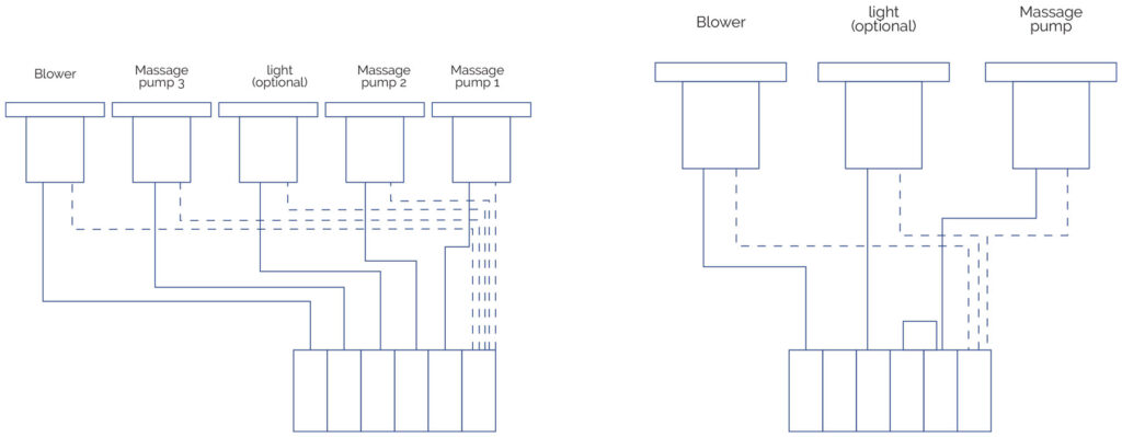
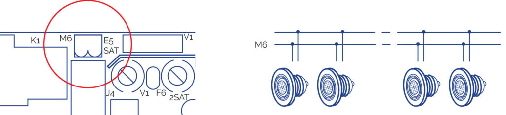
LIGHT
Connect directly to the M6 output of the PCB. Can be switched off or on from the front control panel of the electrical box.
OTHER ELECTRICAL CONNECTIONS