SPA CONNECTION STEPS
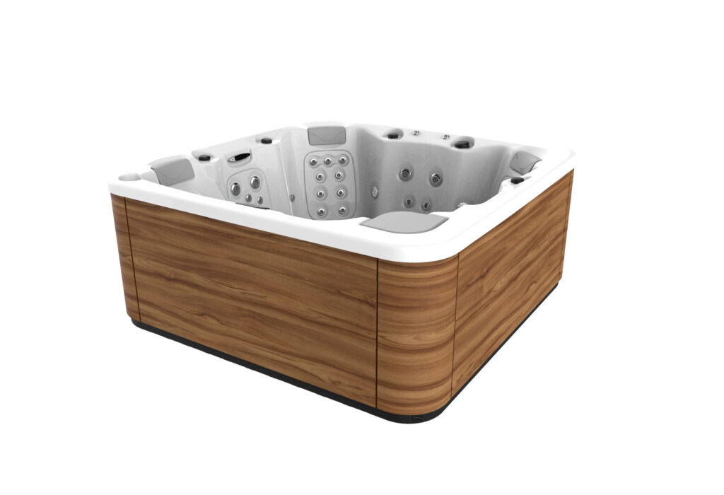
Locate the electrical panel of the Spa.
Locate the electrical control panel; to do this, open the side panel to access the electrical components.
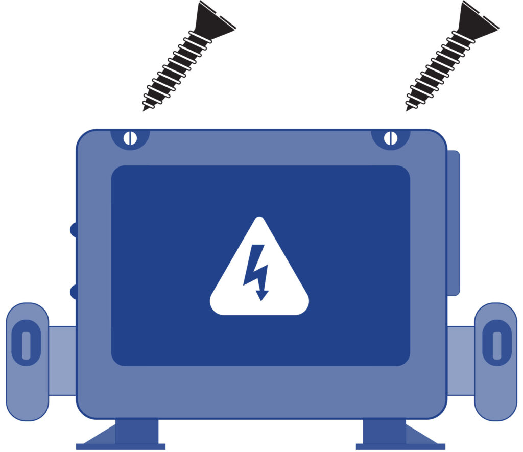
Open the electrical box.
Connect the spa’s electrical control panel to the diferential switch.
INSTALLATION OF THE DIFFERENTIAL
The electrical installation should incorporate a high-sensitive 2-pole differential in the general mains input panel (the differential is not supplied with the Spa).
CONNECT THE ELECTRICAL CONTROL PANEL TO THE DIFFERENTIAL
SWITCH
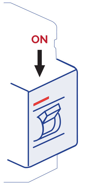
Before carrying out any work on the Spa, make sure it is disconnected from the mains (differential switch in the OFF position, or disconnect the cable from the mains).
Use a suitable cable from the differential switch to the electric cabinet of the Spa, depending on the location and applicable law. The cable section will vary depending on the Spa model and the distance of the installation.
The required kW are indicated in the appendix Technical Specifications of the Spa. The maximum power must be considered, depending on the “High Amp” or “Low Amp” configuration.
DIP Switch Functions
Fixed-Function DIP Switches
A1 Test Mode (normally off).
A2 In “ON” position, add one high-speed pump (or blowe) with Heater.
A3 In “ON” position, add two high-speed pumps (or 1 HS Pump and Blower) with Heater.
A4 In “ON” position, add four high-speed pumps (or 3 HS Pumps and Blower) with Heater.
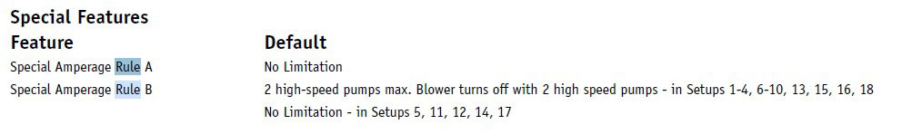
A5 In “ON” position, enables Special Amperage Rule B. See Special Features section under Configuration Options for functionality with your system. In “OFF” position enables Special Amperage Rule A.
A6 Persistent memory reset (Used when the spa is powering up to restore factory settings as determined by software configuration).
A2, A3 and A4 work in combinatio to determine the number of high-speed devices and blowers that can run before the heat is disabled. f.e. A2 and A3 in the ON position and A4 in the OFF position will allow the heater to operate with up to 3 high-speed pumps (or two HS Pumps and Blower) runing at the same time. Heat is disabled when the fourth high-speed pump or blower is turned on.
Note: A2/A3/A4 all ogg = No heat with any high-speed pump or blower.
Assignable DIP Switches
A7 In “ON” position, enables a 5-minutes cool down for some gas heaters (Cooling Time B). In “OFF” position, enables a 1-minute cool down for electric heaters (Cooling Time A).
Undesignted switches are not assigned a function.
The Electric Specification Sheet attached at the end of this manual indicates both the “Low Amp” and the “High Amp” power.
Special Features
CABLE SECTION
To determine the cable section of the electrical installation, see the values indicated in this sheet and the following table:
Kw required
| 2,1 | 2,5 | 2,8 | 3,2 | 3,5 | 4,4 | 5,3 | 6,2 | 7,0 | 7,9 | 8,8 |
Nominal section of the cable in mm2
| Distance | |||||||||||
| 6-11 m | 2,5 | 2,5 | 2,5 | 2,5 | 4 | 4 | 6 | 10 | 10 | 10 | 10 |
| 11-15 m | 2,5 | 2,5 | 4 | 4 | 4 | 6 | 6 | 10 | 10 | 10 | 10 |
| 15-20 m | 4 | 4 | 4 | 6 | 6 | 6 | 10 | 10 | 10 | 16 | 16 |
For longer distances, increase the cable section accordingly.
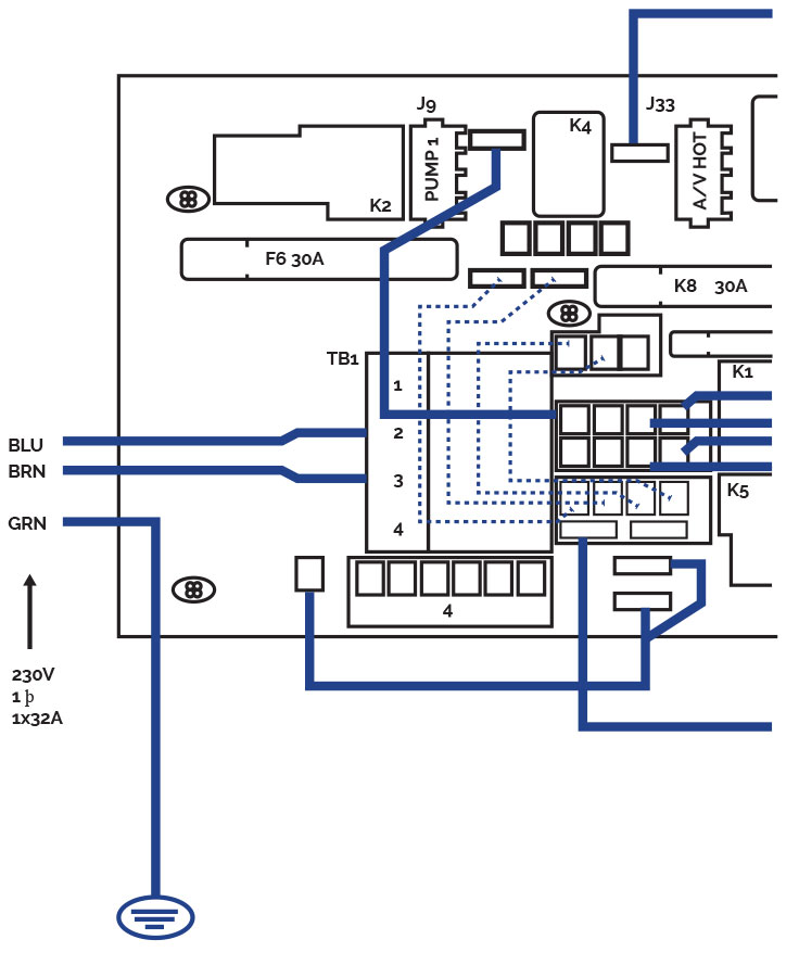
Some configurations may require installing 1 32A line, 2 16A lines or even one three-phase line (3 x 16A) to cover the power required by the Spa.
The different configuration options of the electrical control panel are explained further on in this Installation Manual.
Remember that the installation and any changes in the electric configuration must be carried out by qualified personnel, following the current regulations in each country.
The manufacturer shall not be responsible for any damage caused by an improper installation or an installation performed by non-qualified personnel.
To connect the supply to the electrical panel of the Spa, locate the packing gland positioned at one end of the electrical panel.
Make sure that there is no electric current in the connection cable (differential switch in the OFF position).
Take the cable to the Spa electrical panel.
Open the cover of the electrical cabinet, insert the feed cable through the free side.
Attention: the indicated blue cable is neutral, and the brown cable indicates the line or phase.
Fasten the terminals as indicated in the following diagrams and the type of electrical supply.
Single line
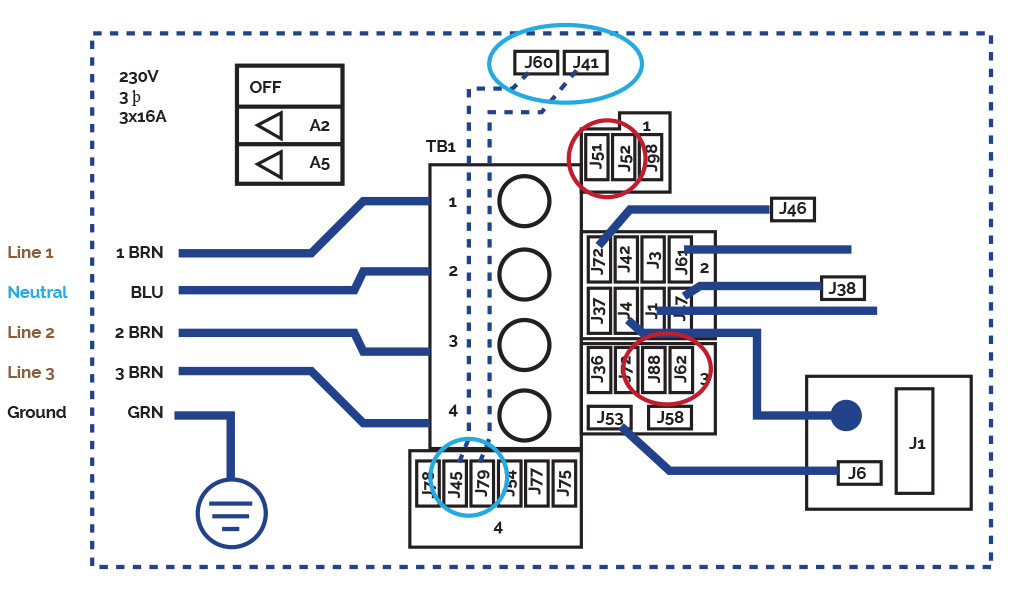
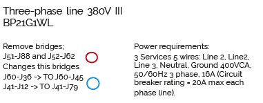
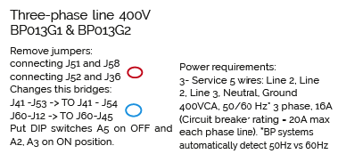
THREE PHASES 400V
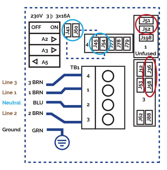
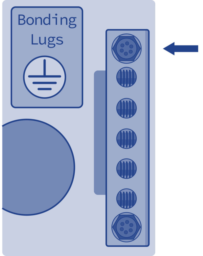
Fasten the earth cable (yellow and green) to the terminal on the outside of the control cabinet as shown in the following diagram: