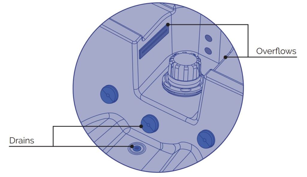
The drain loop consists of two drains that are internally connected in front of the drain solenoid valve (SV). After the SV, the overflow loop is connected to the drain loop and, from there, to the drainage system via the water seal.
When following a continuous water filling process, the hot tub has an overflow loop composed of two overflows that are located above the height of the telescopic filter. They discharge the excess water into the building’s drainage system after it passes through the water seal (not supplied with the spa), regardless of whether the SV is open.
Due to empty the Spa, “Drain” button should be manually pressed.
The water then flows through the drains at the bottom of the hot tub, towards the drain solenoid valve, which remains open for 240 minutes. Then from the SV to the drainage system.
Drain function can be manually interrupted at any time by manually pressing the “DRAIN” button again.
When draining mode is activated, the massage pump is disabled.
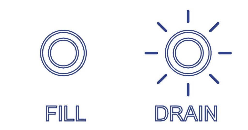
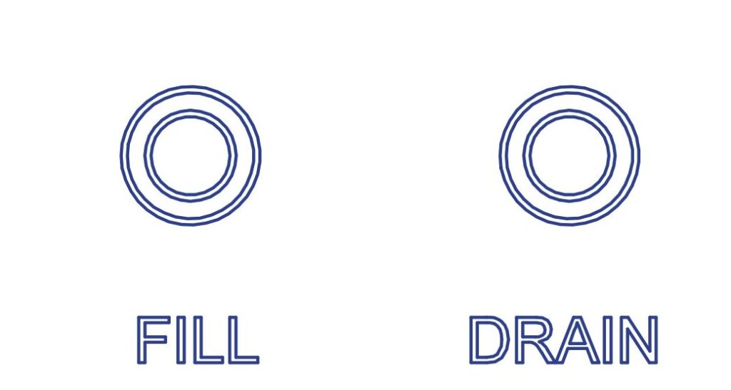
Draining by mechanical switch
Flashing blue lught will be activated during draining cycle (draining mode swith picture).
240 minutes later, drain electrovalve will close automatically (OFF mode) and flashing blue light will turn off.
FAQS
While filling process, draining switch can be activated manualy and filling process is automatically stopped.
While draining cycle, it is not possible to activate the fill switch manualy. Draining switch must be pressed again to turn off and fill switch must be pressed to start new cycle.
In the event of an electrical power failure during filling, the process stops and upon returning mains voltage, filling process turns on and it is stopped until the pre-established maximum water level is detected.
In the event of an electrical power failure during draining cycle, draining electrovalve will remain open and will empty completely. When the mains voltage is restored, draining electrovalve will automatically close for safety.
In the event of an electrical power failure during electrovalve closing process, it will remain in that position; upon returning the mains voltage it will automatically close totally for safety.
Whenever the spa is drained, the filter should be cleaned (and drained/dried when proceeds).
ATTENTION Remember that when you drain your spa not all of the water runs off.
If your spa is not going to be used for long periods, especially in winter, remove any stagnant water on the seats and on the bottom of the spa with a sponge. Any water remaining in the pipes can be sucked out through the water and air nozzles using a liquid suction pump. The pumps must also be emptied through the drain plug.
When preparing to drain the spa, proceed with the following recommended steps described below.
Start draining up to the halfway point of the spa.
Clean any dirty on the surface where stains are visible, such as in the water level mark.
Drain all the water until the spa is totally empty.
After that, the drain and the ground from the spa must be cleaned in order to ensure that no water is left in it.
Regular cleaning is recommended.
See section 6.5. Acrylic care to check the specifications that should be considered regarding the acrylic’s cleaning.