PIPING
The following type of piping should be used for the connection:
*On standard distance (maximums 7 m) and without losing power charge.
Follow the diagrams and assembly instructions given below for each circuit.
In any event, the installation of bends and piping should be reduced to a minimum in order to reduce the load loss of the installation.
Always use plastic accessories, gasket and teflon tape for the selector valve connections. Never use steel accessories or piping as they could seriously damage the plastic components.
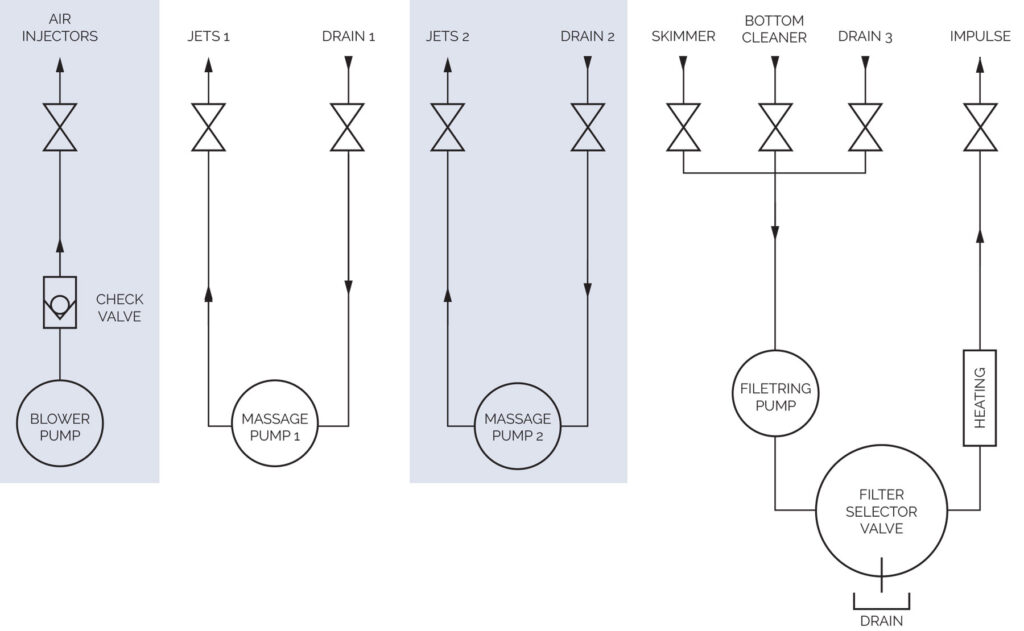
CIRCUIT DETAIL
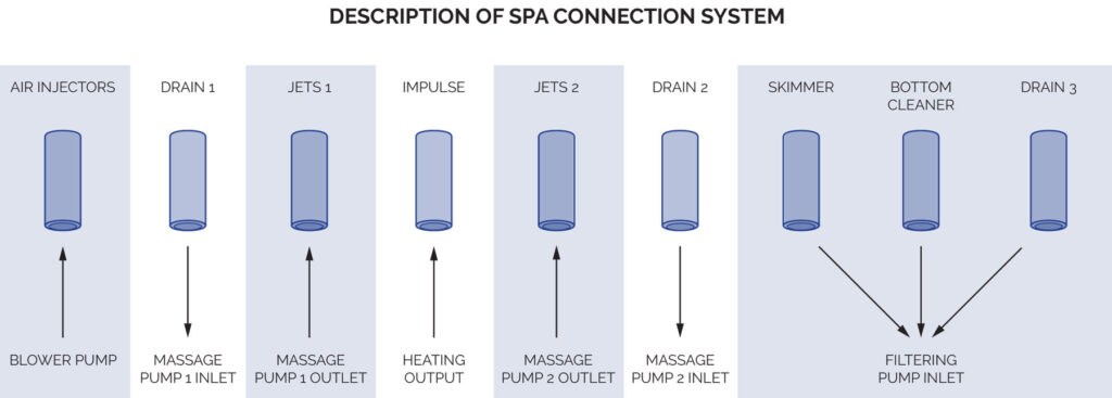
FILTERING CIRCUIT
Connect the suction circuit of the filtering pump to the outlet of the Spa Skimmer, placing two ball valves to stop the water flow if necessary.
Connect the filtering return, the heater outlet, to the impulse inlet of the Spa, placing two ball valves to stop the water flow if necessary.
Make a by-pass in the filtering return circuit to the drain, to enable you to empty this circuit in the event of a breakdown of the heater. It will also be used to empty the spa.
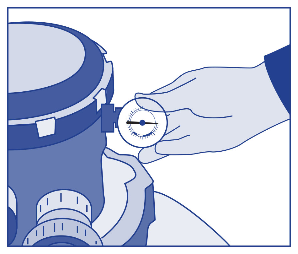
MANOMETER
It is not necessary to use teflon tape, as a joint seals this point. Do not use a tool to tighten the T-part of the pressure gauge, simply tighten it with your hands.
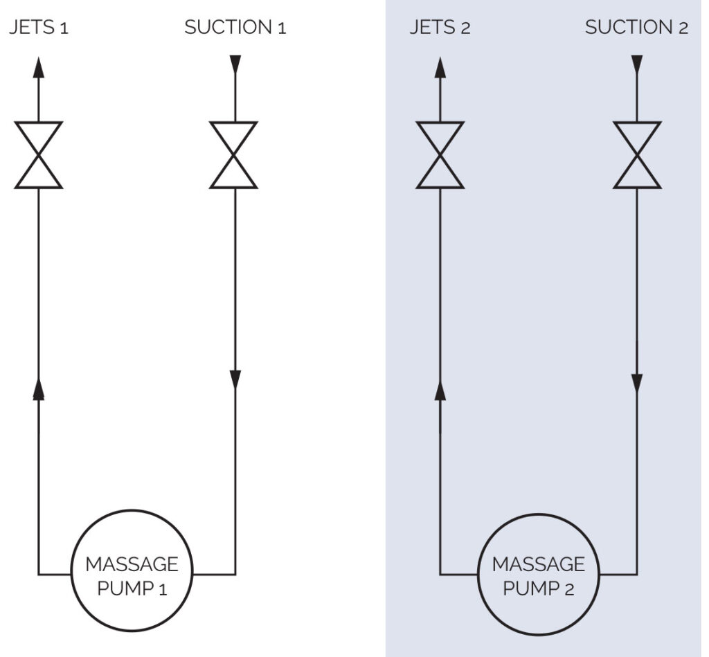
WATER MASSAGE CIRCUIT
Connect the suction circuit of the massage pump to the Sump outlet of the Spa, placing two ball valves to stop the water flow if necessary.
Connect the massage return to the Jets inlet of the Spa, placing two ball valves to stop the water flow if necessary.
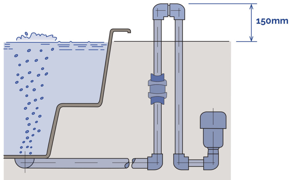
AIR MASSAGE CIRCUIT
The piping of the air circuit should be fitted with a siphon 150 mm above the maximum water level of the spa, placing an anti-return valve between the this siphon and the Spa, as indicated in the connection diagram.