DIFFERENTIAL SWITCH INSTALATION
The electrical installation should be fitted with a 2-pole, high sensitivity differential switch in the general current input panel (the differential switch is not supplied with the Spa).
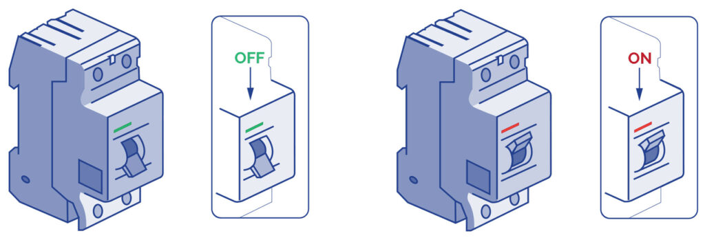
Check that the differential switch is in the OFF position. Do not place the differential switch in the ON position until the Spa is full of water.
Connecting the differential switch to the Kit
Before doing any work on the kit, the electrical power supply should be switched off (differential switch in the OFF position, or disconnect the cable from the mains).
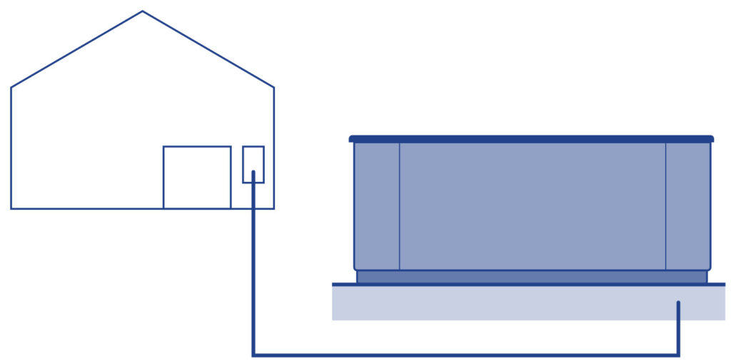
Use appropriate cable from the differential switch to the electrical cabinet of the kit, depending on the type of location where the kit is to be installed, and current applicable law. The cable section will be different depending on the model of kit and the distance of the installation.
HIGH AMP / LOW AMP CONFIGURATION
Depending on the configuration of the kit, the consumption of electricity can vary considerably, and as a result, the installation should match the electric power required.
LOW AMP
This configuration disconnects the electric heater when any massage pump is started-up. This configuration limits the electricity consumption.
Note: LOW AMP is the standard default configuration.
HIGH AMP
With this configuration, all the elements of the kit can operate at the same time. This configuration uses a greater amount of electricity.
LOW AMP / HIGH AMP configurations can be changed using the switches on the electric panel. The configuration options of the electric panel are shown further on in this Manual. For High Amp you should put A2-A3-A4 in On position and A5 in Off position like the picture below.
| SWITCHBANK S1 OFF | SWITCHBANK S1 ON | ||
| DON’T ADD 1 HS PUMP W/HTR | A2▶️ | ADD 1 HS PUMP WITH HEAT | |
| DON’T ADD 2 HS PUMPS W/HTR | ◀️A3 | ADD 2 HS PUMPS WITH HEAT | |
| DON’T ADD 4 HS PUMPS W/HTR | ◀️A4 | ADD 4 HS PUMPS WITH HEAT | |
| SPECIAL AMPERAGE RULE A | ◀️A5 | SPECIAL AMPERAGE RULE B |
LIST OF SECTION, DISTANCE AND POWER REQUIRED
To determine the section of the electrical installation leads, see the values given in the, before mentioned, Electrical Specifications together with the following table:
KW required
| 2,1 | 2,5 | 2,8 | 3,2 | 3,5 | 4,4 | 5,3 | 6,2 | 7,0 | 7,9 | 8,8 |
Nominal section of the cable in mm2
| Distancia | |||||||||||
| 6-11 m | 2,5 | 2,5 | 2,5 | 2,5 | 4 | 4 | 6 | 10 | 10 | 10 | 10 |
| 11-15 m | 2,5 | 2,5 | 4 | 4 | 4 | 6 | 6 | 10 | 10 | 10 | 10 |
| 15-20 m | 4 | 4 | 4 | 6 | 6 | 6 | 10 | 10 | 10 | 16 | 16 |
For greater distances increase the cable section proportionally.
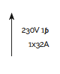
There may be configurations which require the installation of 1 line of 16 A, 1 line of 32 A to cover the power required by the Spa.
The configuration options of the electrical panel are given further on in this Manual.
Please remember that the installation and electrical configuration changes can only be performed by qualified people and always following the current regulations in each country.
The manufacturer is not liable, under any circumstances, for damage caused by incorrect installation or performed by non-qualified people.
To connect the power supply of the Kit, locate the free packing gland at one end of the Automatic – Manual Selector panel.
Make sure that there is no electrical current in the connection cable (differential switch in the OFF position).
Take the cable to the panel of the Kit.
SINGLE LINE (1 X 16 A) LOWAMP OR (1 X 32 A) HIGHAMP:
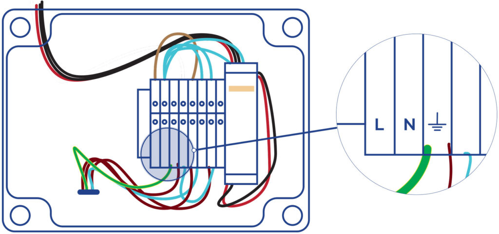
Open the cabinet of the Automatic – Manual Selector, insert the cable through the free packing gland and connect the Neutral marked with N, the line or phase to the terminal marked L and the earth in the special, green and yellow, earth terminal.
With the HIGH AMP option, the heater of the compact equipment always operates when temperature is required (meaning a higher electrical consumption).
With the LOW AMP option, the heater is limited to the filtering cycles (reducing electrical consumption to a minimum).